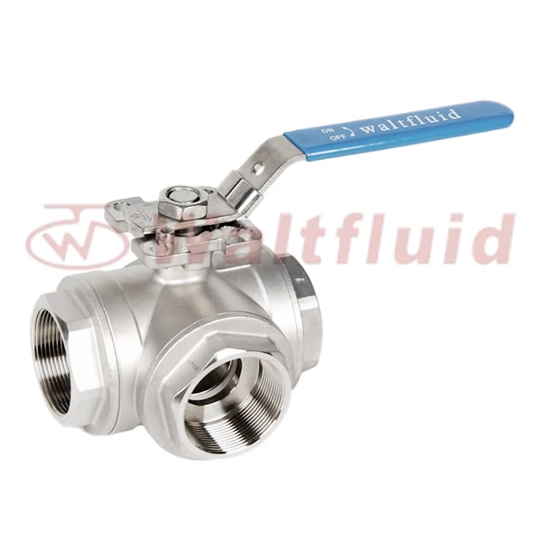
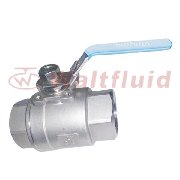
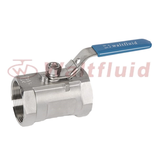
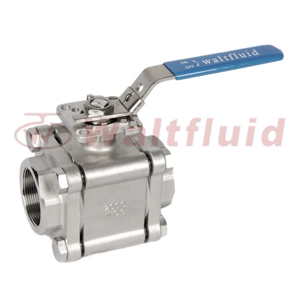
Professional Production Of 3 Piece Threaded Ball Valve Repair Method
Causes of Leakage in 3 Piece Threaded Ball Valve and Bonnets:
1. Poor casting quality, with defects such as pinholes, loose structures, and slag inclusions on the valve body and bonnet.
3. Poor welding, with defects such as slag inclusions, unwelded areas, and stress cracks.
4. Damage to the cast iron after being struck by heavy objects.
Maintenance Methods:
1. Improve casting quality and strictly perform strength tests according to regulations before installation.
2. Valves operating at temperatures of 0°C or below should be insulated or heated, and valves out of service should be drained of accumulated water.
3. Welds on valve bodies and bonnets should be welded according to relevant welding procedures, and flaw detection and strength tests should be performed after welding.
4. Do not place or push heavy objects on the valve. Do not strike cast iron or non-metallic valves with hammers. Large-diameter valves should be installed with brackets. Leakage at the packing: Leakage at the packing accounts for the largest proportion of valve leakage. Causes:
1. Improper packing selection, inability to withstand the corrosive media, high pressure or vacuum, or high or low temperature conditions of the valve.
2. Improper packing installation, such as using a smaller packing instead of a larger one, poor spiral joints, or packing that is tight at the top and loose at the bottom.
3. Packing that has exceeded its service life, aging, and loss of elasticity.
4. Valve stem precision is low, with defects such as bending, corrosion, and wear.
5. Insufficient packing turns, resulting in insufficient gland tightening.
6. Damage to the gland, bolts, or other components, preventing the gland from tightening.
7. Improper operation, such as excessive force.
8. The gland is skewed, or the gap between the gland and the valve stem is too small or too large, causing valve stem wear and packing damage. </span></p>
Maintenance Methods:
1. Select the packing material and type according to the operating conditions.
2. Install the packing correctly according to relevant regulations. The packing should be installed and tightened turn by turn, and the joint should be at 30° or 45°.
3. Replace packing that has been in service for an extended period of time, is aged, or is damaged.
4. Straighten and repair bent or worn valve stems, and replace any severely damaged ones promptly.
5. Install the packing according to the specified number of turns. Tighten the gland symmetrically and evenly, and allow a preload clearance of at least 5mm for the gland sleeve.
6. Repair or replace damaged glands, bolts, and other components promptly.
7. Follow operating procedures. Except for the impact handwheel, operate with a constant speed and normal force.
8. Tighten the gland bolts evenly and symmetrically. If the clearance between the gland and the valve stem is too small, increase it appropriately. If the clearance between the gland and the valve stem is too large, replace it.
Sealing Surface Leakage
Causes: 1. The sealing surface is unevenly ground, failing to form a seal line;
2. The center of the valve stem and the closure member is suspended, misaligned, or worn;
3. The valve stem is bent or improperly assembled, causing the closure member to be skewed or misaligned;
4. Improper sealing surface material quality or the valve is not selected for the operating conditions.
Maintenance Methods:
1. Select the correct material and type of gasket based on the operating conditions;
2. Carefully adjust and operate smoothly;
3. Tighten bolts evenly and symmetrically. Use a torque wrench if necessary. The preload force should meet the requirements and should not be too high or too low. Flanges and threaded connections should have a certain preload clearance.
4. Gaskets must be aligned and evenly loaded when assembled. Overlapping gaskets and the use of double gaskets are not permitted.
5. Static sealing surfaces that are corroded, damaged, or poorly finished should be repaired, polished, and color-checked to ensure they meet the relevant requirements.
6. Gaskets must be clean during installation. The sealing surfaces should be cleaned with kerosene, and gaskets should not fall to the ground.
Leakage at the Sealing Ring Connection
Causes:
1. The sealing ring is not tightly pressed;
2. The sealing ring is welded to the body, and the weld overlay quality is poor;
3. Loose threads, screws, or pressure rings connecting the sealing ring;
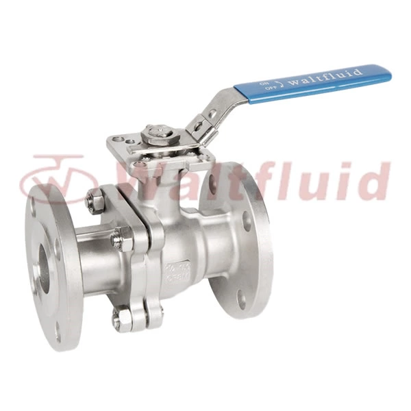
4. The sealing ring is corroded. The multi-positioning high-platform ball valve consists of a platform, a valve stem, a handle, a stopper, a locking plate, a compression nut, and a cylindrical locating pin. The multi-positioning high platform features two independent rectangular slots and two connecting rectangular slots. The two independent slots serve as the locking plate slots for closing and opening the valve. The two connecting rectangular slots are connected by a 90-degree arc surface. The stopper is mounted on the stem stop shoulder via the handle and clamped to the connecting rectangular slot by a compression nut. The depth of the two independent rectangular slots is one stopper thickness lower than the positioning platform surface, while the depth of the two connecting rectangular slots is one stopper thickness lower than the positioning platform surface. The upper portion of the stopper is lower than the top of the positioning platform, while the lower portion is higher than the bottom plane of the slot. The handle can be flat or curved. Due to this structure, the ball valve has multiple positioning methods and a wide range of applications.
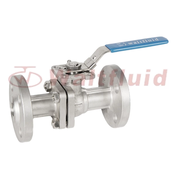
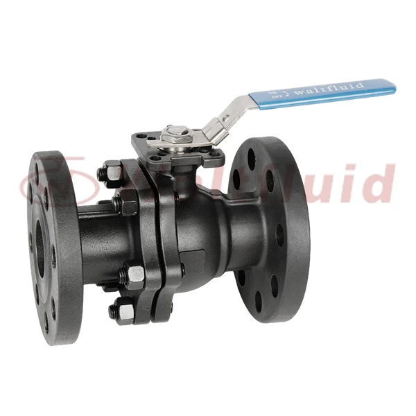
The high-platform ball valve consists of a valve body and a valve seat. The valve body and valve seat are sealed together using stud bolts and nuts via a center gasket. A ball is positioned within the inner cavity of the valve body, and the upper end of the ball is attached to the valve stem. A stainless steel gasket and packing are also located below the packing where the stem and upper end of the valve body meet. The upper portion of the packing is secured to the valve body via a gland using external hexagonal bolts and nuts. This high-platform ball valve eliminates the need for tapping the actuator bracket and gland bolts. The actuator bracket is now integrated with the valve, eliminating the need for custom mounting brackets; the valve and actuator can be directly installed. The gland bolt mounting area of the valve body features a U-shaped groove, allowing nuts to be inserted directly into the U-shaped groove and installed using external hexagonal bolts. If leakage is detected after excessive operation, the hexagonal bolts can be adjusted directly with a wrench, significantly improving production efficiency.
 English
 中文
中文 Pусский
  Español
